
SV572 - Introduction
This page has strayed from the main amplifier page in order to elaborate on the SV572 without cluttering the general amplifier page.
Just to recap, act 2 of the SV572 ended with a breadboard which incorporated a change to fixed bias. After nearly 5 years of kicking around and taking up space it had to be tidied up and put in a box.
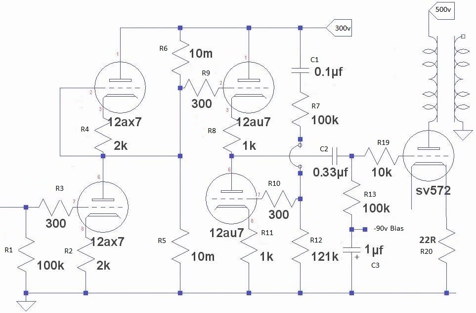
Act 3 involves the introduction of: a solid state rectifier, a new choke-input power supply, a new bias scheme, dc heating, an HT delay and double voltmeter to assist in biasing. The driver circuit is still the original aikido circuit using ecc82 and ecc83, designed by John Broskie.

breadboard version 2

breadboard version 3
new circuit

new ps circuit
The chassis
A Hammond 17 x 12 x 3
Small holes less than 5mm have been centre punched and drilled directly with a block of wood beneath
Larger holes, 5-12mm have been drilled at 5mm and then enlarged with a stepper drill
Largest holes are made with a hole punch, i.e valve socket holes.
Square holes have been made with a 6mm drill and jig saw.
Immaculate paint job once again by Dave Tuplin of T&G Motors in Alford, Lincs

bare front

bare back

paint front

paint back
Fixed bias
The fixed bias scheme was originally run from the HT transformer. With the introduction of the delayed start on the HT transformer this method was no longer possible, so a new circuit was constructed. In the circuit shown the bias is adjustable from approximately -65v to -120v(mains at 250v), which is entirely adequate for swapping between SV811 and SV572. Locating small 72v transformers proved difficult so 2 transformers with 2 x 0-18v secondaries were used, with all secondaries wired in series. The circuit board was constructed so that the screw adjusters were accessible from the top of the chassis, eliminating the need to get inside to re-bias. Monitoring the bias is achieved via the voltmeters shown on the LCD.

circuit

board top

board bottom

chassis access
DC heating
Previous versions had presented a degree of hum, especially when partnered with efficient loudspeakers so it seemed like a good opportunity to introduce some dc heating. Having made the decision it was decided to go all the way, and this resulted in the inclusion of Rod Coleman's regulator boards. These are available in kit form from Rod directly(search for Lyrima Ltd on the internet for contact details). The regulator boards still require a power supply, which with these valves is not trivial, no gain without pain. The heatsinks are from Conrads. The transformer used was a frame type which happened to be in the bit box. Without one to hand this may well have ended up as a toroid, as research has shown they are slightly less bulky.

ps circuit

ps board

regulator board

back chassis
HT delay and bias measurement.
Originally this amp was going to have a basic delay circuit based on the 555 timer chip. Thinking about how to implement a voltmeter at the same time resulted in research of the AVR 8 bit microcontrollers. The voltmeter is required to bias the sv572 output valves. The AVR chip, ATTINY461, can do both jobs without breaking into a sweat. For more detail on the AVR chip see the LCD paragraph below. This is an indulgence, having not played with embedded chips since the 1970s this became very tempting. Nah, it became an obsession. It wasn't an entirely useless diversion though, as an IR remote control passive pre-amp is on the workbench using the same technology. Anybody using this method would probably use a 5v relay and remove the need for the 12v regulator. The 12v relay was all I had at the time. For practical reasons the relay switches the mains to the HT transformer, rather than the HT itself.

circuit
board layout

board top

board bottom
Finished amplifier
Probably not the most elegant layout, but it is symmetrical. The output transformers are James 6123 and the power transformer are bespoke windings from BLS and the chokes are Hammond, supplied by Bluebell.

front

back

bottom

thd
The LCD and micro-controller
Acknowledging the fact that the LCD is an indulgence and a bit of an overkill, it still fulfills the original requirement of providing a 30 second delay for the HT and provides 2 voltmeters to monitor the bias current on the output valves. The AVR microchip contains an ADC which is capable of measuring up to 5 volts directly, without resorting to divider circuits. As a consequence, by placing the correct value of sense resistor on the output valve cathode then a measurable voltage can be produced. Considering the LCDs are available for less than £2 and the AVR micro chips cost £1.50, then the only real indulgence is the time spent writing the code.
If anybody is interested in trying this method then the AVR code is available
here. If unfamiliar with microcontrollers generally then be aware
that some hardware will be needed to get the program into the chip after it has been compiled. A free compiler is available from the Atmel site here, and cheap programmers(under£10) can be found by searching for 'attiny programmer' on any search engine.
Please use the Contact page to request further details.